The splitter finally showed up. This session was about seeing if the signal chain actually worked end to end — Apple TV → splitter → TV + B101 — and getting at least one real captured frame out of it. No LEDs wired yet, just proving the capture side works and figuring out the layout.
Getting the B101 to see the signal
First step after wiring everything up was setting the EDID so the B101 knows what kind of signal to advertise to the Apple TV:
v4l2-ctl -d /dev/v4l-subdev0 --set-edid=type=hdmi,pad=0
The TV blipped out for about 3 seconds and came back — that’s the HDMI re-handshake, expected. After that the B101 was reporting a stable 1080p60 timing, which felt promising:
v4l2-ctl --query-dv-timings -d /dev/video0
Active width: 1920
Active height: 1080
Pixelclock: 148500000 Hz (60.00 frames per second)
Applied the timings, checked the media graph — TC358743 → unicam path looked correct. Tried to capture a frame.
1080p60 didn’t work
v4l2-ctl -d /dev/video0 \
  --set-fmt-video=width=1920,height=1080,pixelformat=UYVY \
  --stream-mmap=3 --stream-count=1 \
  --stream-to=/tmp/frame.uyvy
VIDIOC_STREAMON returned -1 (Invalid argument)
Zero byte output file. The kernel log had this:
Device has requested 3 data lanes, which is >2 configured in DT
That explained it. The TC358743 wants 3 CSI lanes for 1080p60, the Pi 3 device tree only has 2 configured. The chip can detect the signal fine — locking timings is a chip-level thing — but streaming through the unicam pipeline is where it fell apart. Might be fixable with a device tree overlay, but I didn’t go down that rabbit hole today.
Switching to 1080p30
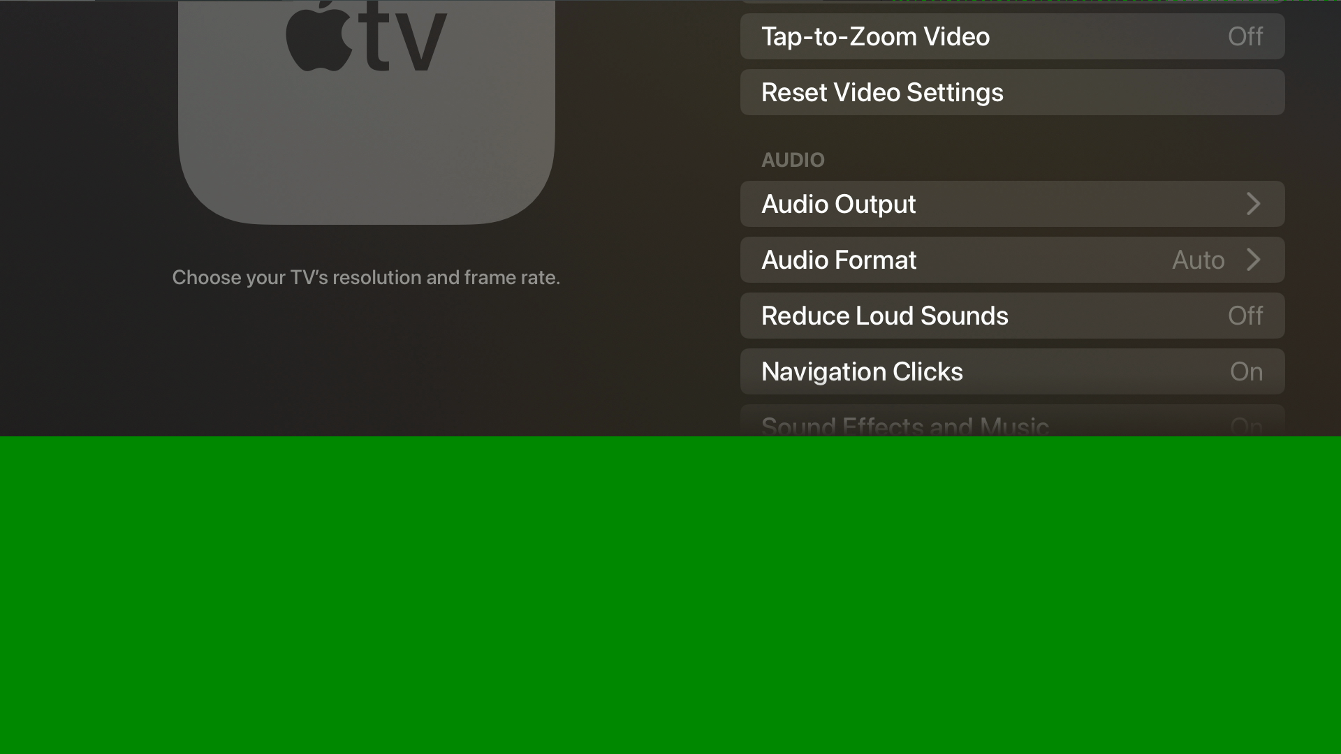
On the Apple TV: Settings → Video and Audio → Resolution → Other Resolutions → 1080p SDR 30Hz.
The B101 immediately dropped to:
Pixelclock: 74250000 Hz (30.00 frames per second)
Tried the capture again with the updated timings and it worked:
v4l2-ctl --query-dv-timings -d /dev/video0
v4l2-ctl --set-dv-bt-timings query -d /dev/video0

v4l2-ctl -d /dev/video0 \
  --set-fmt-video=width=1920,height=1080,pixelformat=UYVY \
  --stream-mmap=4 --stream-count=1 \
  --stream-to=/tmp/frame.uyvy
-rw-rw-r-- 1 derek derek 4.0M May 3 00:21 /tmp/frame.uyvy
4.0 MB is exactly right — 1920 × 1080 × 2 bytes = 4,147,200 bytes. One full UYVY frame.
Converting to PNG, first attempt was green
ffmpeg -y -f rawvideo \
  -pixel_format uyvy422 \
  -video_size 1920x1080 \
  -i /tmp/frame.uyvy \
  -frames:v 1 -update 1 \
  /tmp/frame.png
PNG produced, but the bottom half was green — visually corrupted. The file size was correct, so the capture path was working. My guess is the TC358743/unicam pipeline needs a few frames to stabilize after stream start and the first one is unreliable.
Captured 10 frames instead and pulled the 9th:
v4l2-ctl -d /dev/video0 \
  --stream-mmap=4 --stream-count=10 \
  --stream-to=/tmp/capture10.uyvy
Worth noting: v4l2-ctl doesn’t produce numbered files. The %03d in --stream-to is treated literally — you get one 40 MB concatenated file (10 frames × 4,147,200 bytes). Extract frame 9:
ffmpeg -y -f rawvideo \
  -pixel_format uyvy422 \
  -video_size 1920x1080 \
  -i /tmp/capture10.uyvy \
  -vf "select=eq(n\,9)" \
  -frames:v 1 -update 1 \
  /tmp/frame-last.png
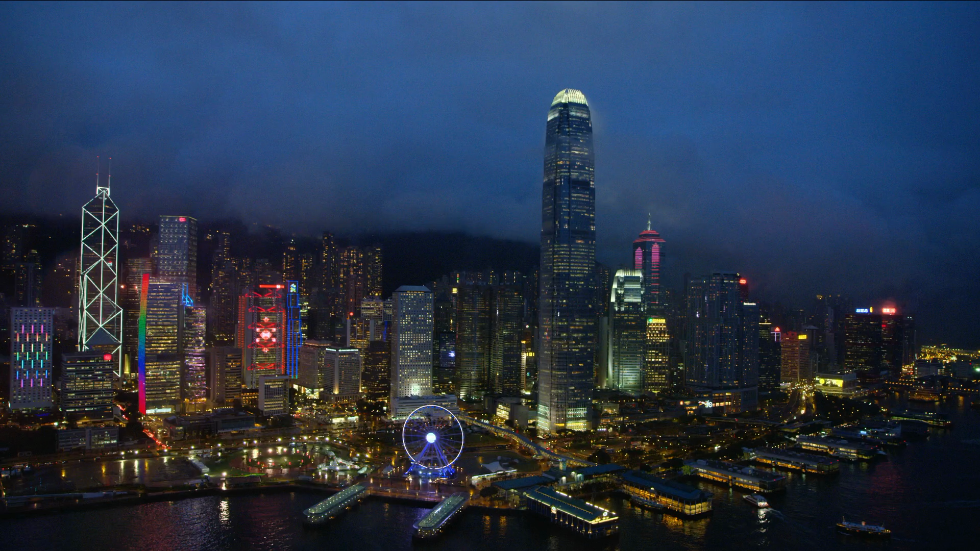
That came out clean.
Copied it off to verify:
# from Mac
scp derek@hyperion.local:/tmp/frame-last.png ~/Desktop/hyperion-frame-last.png
Hyperion preview
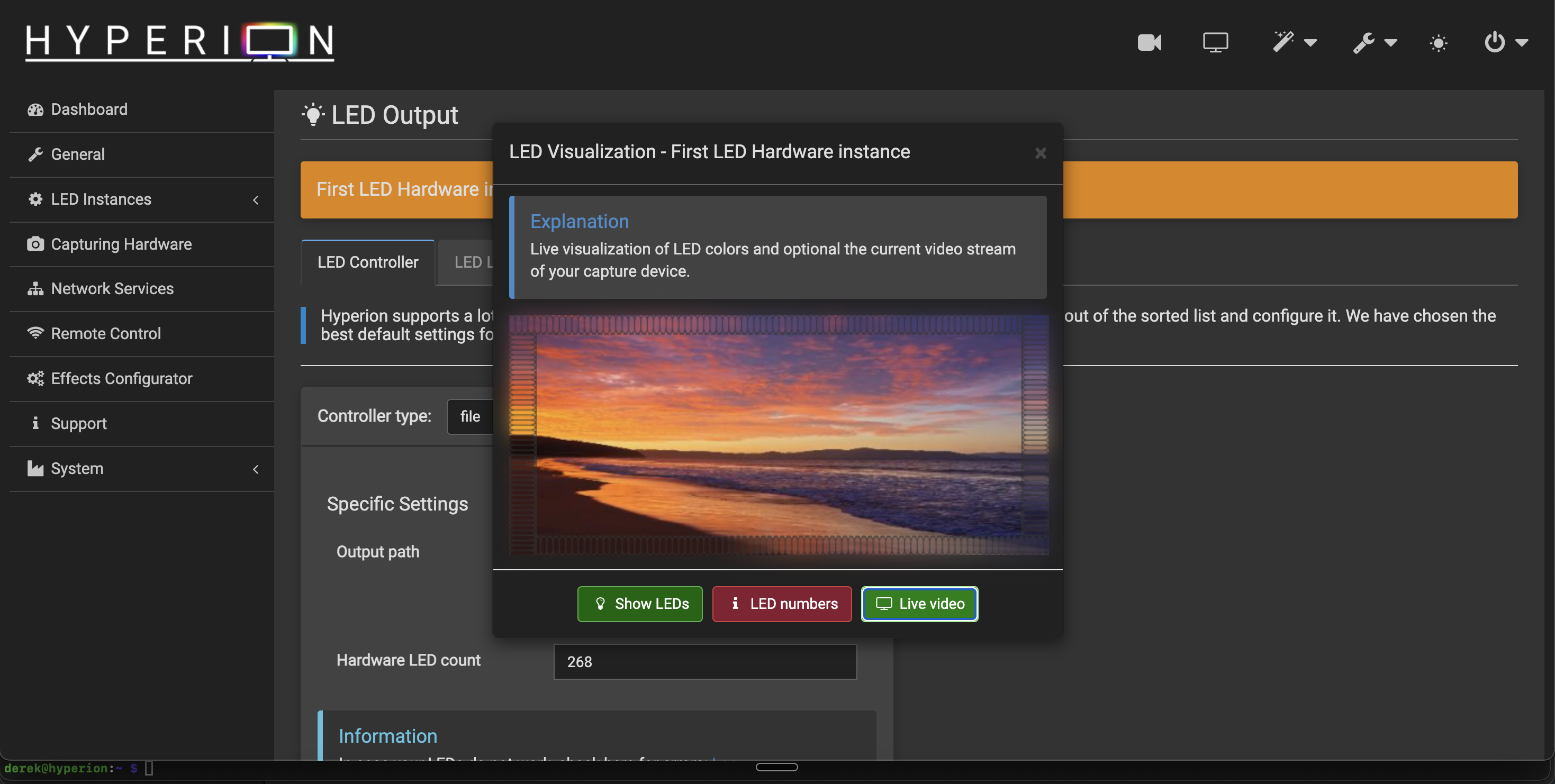
Started Hyperion, opened the dashboard in Chrome. The live video preview was working — virtual LED border reacting to actual Apple TV content, colors moving with the screen. That confirmed the full capture-to-color pipeline inside Hyperion is functional.
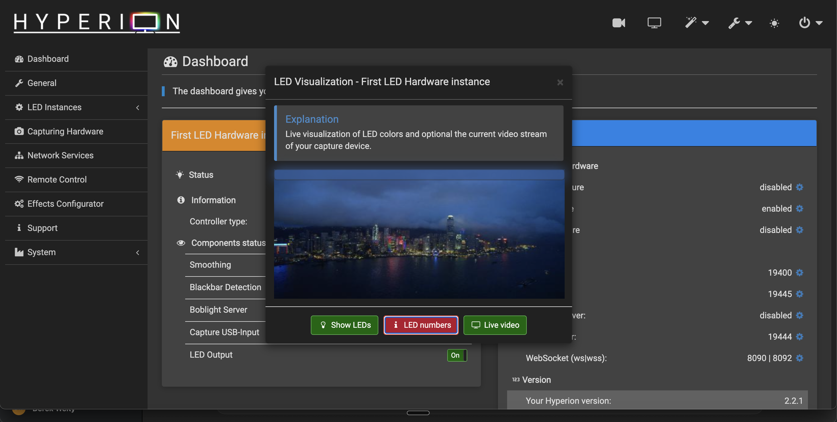
There was something that looked like a corrupted band at the top of the preview. Turned out to be the LED number overlay Hyperion renders in the preview UI, not a capture artifact. The raw frame check had already confirmed the B101 output was clean.
A few non-blocking log lines worth knowing about if you hit them:
libcec.so.6: cannot open shared object file
LED mapping area(s) have a huge number of pixels to be processed. Every 2 pixels will be skipped.
CEC isn’t being used, audio capture isn’t part of this setup, and the LED mapping warning is about Hyperion processing load — not a problem.
LED layout planning
Hyperion’s default virtual layout was 86/86/48/48 (top/bottom/left/right = 268 LEDs). Measured the TV physically and the sides are probably closer to 40 each — the TV isn’t as tall as the default assumed.
Rough plan:
| Edge | Count |
|---|---|
| Top | 80 |
| Bottom | 80 |
| Left | ~40 |
| Right | ~40 |
| Total | ~240 |
With 80 on top and bottom, corner positions work out to:
0   = top-left
80  = top-right
128 = bottom-right
208 = bottom-left
Data input will be at bottom center — position 168 (128 + 40). I’ll run the strip starting there, going toward bottom-left first, then up the left side, across the top, down the right side, back to center. Clockwise from the front.
If the physical direction doesn’t match Hyperion’s layout I’ll just flip it in software rather than rewire.
Hyperion estimated max current for the default 268-LED layout at 17.7A (~88W at 5V), which made it obvious the strip needs its own power supply. That part wasn’t a surprise.
Next
Still need to actually wire and mount the LEDs — that’s the next session. Before then, set the Hyperion layout to match the planned counts, input position 168, and figure out exactly how many LEDs fit on the left and right sides once I’m measuring against the physical TV.
Known-good capture config
| Setting | Value |
|---|---|
| Apple TV output | 1080p SDR 30Hz |
| Pixel clock | 74.25 MHz |
| V4L2 format | UYVY 4:2:2 |
| Frame size | 4,147,200 bytes |
| Reliable frame | Capture 10, extract frame 9 |
1080p60 detects fine but fails at STREAMON — CSI lane issue, probably solvable with a DT overlay but haven’t tried.